
IPC477D PRO 6AV7250-3EC07-0HA0 Touch Digitizer Glass

| Categories | SIMATIC IPC 477 |
|---|---|
| Brand | VICPAS |
| Model | 6AV7250-3EC07-0HA0 |
| Touch screen panel type | Capacitive |
| Size | 19 inch |
| Brand | Siemens |
| Warranty | 365 Days |
| Product Number | 6AV72503EC070HA0 |
| Product Line | SIMATIC IPC477D PRO |
| Shipping | 2-4 Days |
| Supply Part | HMI Touch Glass |
| FOB port | Guangzhou, Shenzhen, Hongkong |
| Terms of Payment | Western Union, T/T, PayPal, Credit Card |
| Update Time | Dec 22,2024 |
SIMATIC IPC 477D PRO 6AV7250-3EC07-0HA0 Touch Screen Display Replacement Repair

Notes on connecting
The on/off switch does not isolate the device from the power supply. Risk of electric shock if the device is opened incorrectly or defective. There is also a risk of fire if the device or connecting lines are damaged. This will also damage the Siemens IPC477D PRO 6AV7 250-3EC07-0HA0 Touch Screen Glass.
You should therefore protect the Simatic 6AV72503EC070HA0 Touch Panel as follows:
• Always pull out the power plug when you are not using the device or if the device is defective. The power plug must be freely accessible.
• Connect the device to a protective conductor as instructed.
• Use a central isolating switch.
The connection of I/O devices can cause faults in the device. The result may be personal injury and damage to the IPC 477D PRO 6AV7250-3EC07-0HA0 HMI Touch Glass.
Note the following when connecting I/O devices:
• Read the documentation of the I/O devices. Follow all instructions in the documentation.
• Only connect I/O devices which are approved for industrial applications in accordance with EN 61000-6-2 and IEC 61000-6-2.
• I/O devices that are not hotplug-capable may only be connected after the device has been disconnected from the power supply.
Regenerative feedback of voltage to ground by a connected or installed component can damage both the device and Siemens 6AV7 250-3EC07-0HA0 Touch Dgitizer Glass. Connected or built-in I/Os, for example, a USB drive, is not permitted to supply any voltage to the device. Regenerative feedback is generally not permitted or it will do harm to 6AV72503EC070HA0 MMI Panel Screen.
Specifications:
The table below describes the parameters of the Siemens IPC 477D PRO 6AV7250-3EC07-0HA0 Touch Membrane.
| Resolution: | 1366 x 768 Pixels |
| Front Panel: | IP65 |
| Part Number: | 6AV7 250-3EC07-0HA0 |
| Warranty: | 365 days Warranty |
| Touch Type: | Capacitive |
| Environment: | Free From Corrosive Gases |
| Brand: | Siemens |
| Touch Size: | 19'' |
| Relative Humidity: | 90% |
| Storage Temperature: | -20~60°C |
Related SIMATIC IPC477 Series HMI Part No. :
| SIEMENS IPC477 HMI | Description | Inventory status |
| 6AV7250-3EC07-0HA0 | SIMATIC IPC 477D PRO Touch Screen Monitor | In Stock |
| 6AV7250-6GD07-0PA0 | SIEMENS IPC477D PRO MMI Touch Screen Repair | Available Now |
| 6AV7250-7ED07-0PA0 | SIMATIC IPC 477D PRO Touch Digitizer Replacement | In Stock |
| 6AV7250-0FB03-0BA0 | SIMATIC IPC477D PRO Touch Screen Replacement | Available Now |
| 6AV7254-3DD00-0AS0 | SIMATIC IPC 477D PRO Touch Panel Replacement | In Stock |
| SIMATIC IPC477 HMI | Description | Inventory status |
SIMATIC IPC477 Series Manuals PDF Download:
FAQ:
Question: How to protect my Siemens 6AV7250-3EC07-0HA0 Touch Screen Monitor from Burn-in effect?
Answer:
• Switch on the screensaver. The backlight brightness is reduced while the screensaver is active.
• You should also reduce the backlighting.
• Observe the backlighting operating time.
Question: How to mount the device?
Answer:
Prepared for support arm or stand without extension elements (flange on top)
1. If an adapter plate for the Siemens base adapter is included in your support arm system, attach the adapter plate to the support arm with 4 M6x12 screws. Pay attention to the torque that is specified for the support arm.
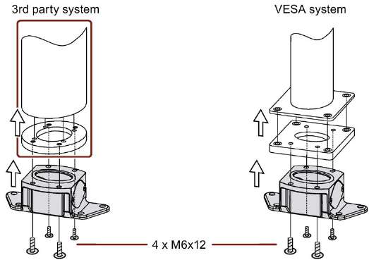
2. Attach the base adapter with 4 M6x12 screws to the mechanical interface of the support arm from below. Pay attention to the torque that is specified for the support arm.
3. Remove the screws ⑤ of the terminal compartment cover.
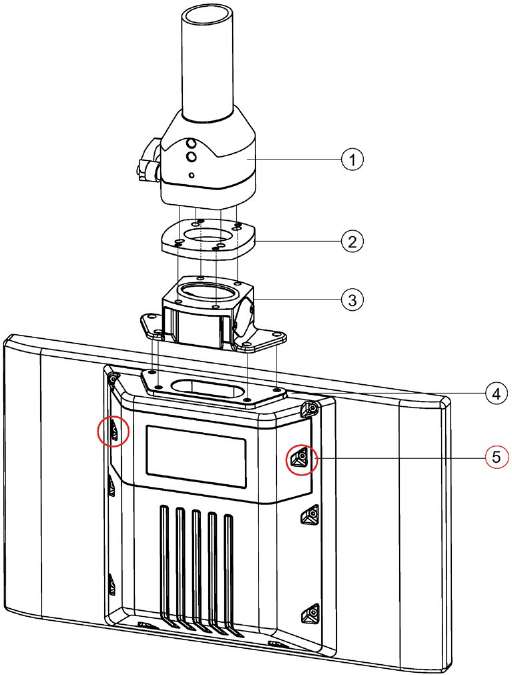
① Support arm head
② Intermediate plate
③ Base adapter
④ Countersunk head screws for device
⑤ Screws for terminal compartment cover
4. Open the terminal compartment cover ⑤ and set it aside safely.
5. Insert all connection cables through the opening of the PRO device.
Make sure that the connecting cables are not damaged.
Recommendation: Route large connectors (e.g. RS232 connectors) and their cables through the pedestal or support arm first.
6. Attach the device with 4 M4x12 countersunk head screws to the base adapter ③ from the top, torque 2.5 Nm.
Make sure that the connecting cables are not pinched.
7. Connect all cables according to the description in the section Connecting the device.
8. Fasten the cover plate ⑤ to the device with the 2 screws, torque 1.5 Nm.
Check that the seal is sitting correctly.
Prepared for support arm and extension elements (flange mount)
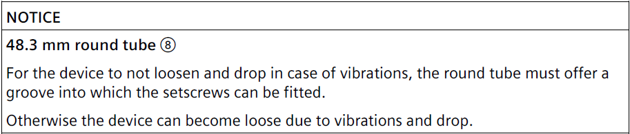
The following description shows an example of how to attach the PRO device to a support arm system using the optionally available Siemens flange mount ⑦. Mounting to a 48.3 mm round tube ⑧ that fits the opening of the PRO device is performed in a similar fashion.
1. Remove the screws ⑤ of the terminal compartment cover.
2. Open the terminal compartment cover and set it aside safely.
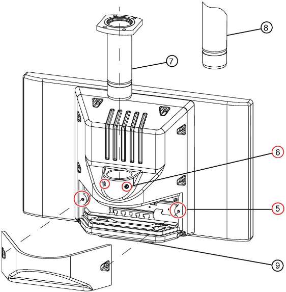
⑤ Screws for terminal compartment cover
⑥ Setscrews
⑦ Flange mount (not included in the product package; see System components
⑧ Third-party round tube (∅ 48 mm)
⑨ Cover plate
3. Grease the flange mount ⑦ or 48.3 mm round tube ⑧ with grease suitable for NBR seals, and insert the flange mount ⑦ or 48.3 mm round tube ⑧ into the corresponding opening of the PRO device.
Make sure that the sealing ring (O-ring) is not damaged. Fasten the flange mount with the 2 setscrews ⑥ M8x10 from the accessory kit.
Observe the appropriate torque:
– Siemens flange mount ⑦: 8 Nm
– 48.3 mm round tube of steel ⑧: 8 Nm
– 48.3 mm round tube of aluminum ⑧: 5 Nm
4. If an adapter plate ⑨ for the Siemens flange mount is included with your support arm, attach the adapter plate to the support arm with 4 M6x12 screws. Pay attention to the torque that is specified for the support arm.
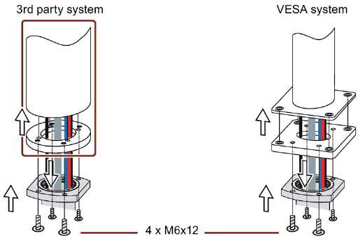
5. Insert all connection cables through the opening of the flange mount or 48.3 mm round tube into the connection compartment of the PRO device. Make sure that the connection cables are not damaged.
6. Attach the device with 4 M6 screws, 16 mm to 20 mm long, to the support arm from below.
The screws are not included in the product package of the PRO device.
Pay attention to the torque that is specified for the support arm.
Make sure that all connecting cables are fed through the flange mount into the interior of the device without damage.
7. Connect all cables according to the description in the section Connecting the device.
8. Fasten the cover plate ⑤ to the device with the 2 screws, torque 1.5 Nm. Check that the seal is sitting correctly.
9. Fasten the cover plate ⑨ from the PRO device product package with 4 M4x12 screws, torque 1.5 Nm.
Alternatively, you can extend the PRO device by adding an Extension Unit at the bottom.
Read the associated documentation.
Common misspellings:
AV7250-3EC07-0HA06AV7250-3EC077-0HA0
6AV750-3EC07-00HA0
6AV7250-03EC07-0HA0
6AV7520-3EC07-0HA0
- Loading...


- Tel
- *Title
- *Content
 Fast Quote
 Fast Quote
 Worldwide Shipping
 12 Months Warranty
 Customize Service
- Tel
- *Title
- *Content
